We offer biaxial geogrid products for embankment for Jordan
A vertical cutoff could be installed in the dike body to mitigate against seepages at location where cracks are expected to cross the dike body (i.e. junction between existing and new dike, location of deep transverse cracks and zones of high differential settlement behavior.
The following methods describing the proposed options for deep cracks treatment:
1- Construction of impervious core parallel to dike C.L using a flexible 1.5 mm LLDPE geomembrane. The geomembrane will create a continuous impervious barrier running all along the longitudinal axis of the dam from the bottom of stage 2 up to the DIKE crest. The geomembrane will be placed in a zigzag pattern as shown below.
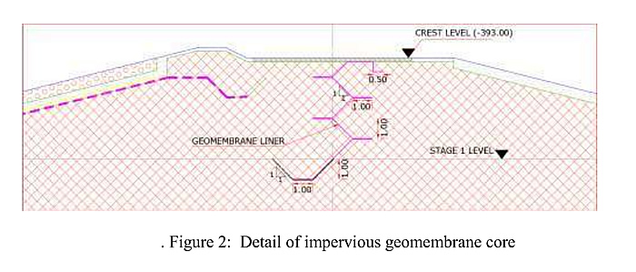
Figure 2: Detail of impervious geomembrane core
2- Construction of cutoff wall in the dam body using steel sheet piles extending from crest level down to natural ground level. Sheet piling through the dike body may require predrilling in order to drive properly the sheet piles to the required depth.
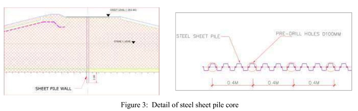
Figure 3: Detail of steel sheet pile core
3- Using of geogrid reinforcement to be placed over or beneath the top surface of stage 1 at locations of treated or expected cracks prior.
GEOGRID SOIL REINFORCEMENT
A. Biaxial Geogrid to be placed below new fill at locations where cracks are re appearing after being treated and at location of treated sinkholes, the geogrid is aimed to redistribute the stresses on the base of the embankment and to reduce the settlement and differential settlement and the possibility for cracking along its life time.
B. The reinforcing element shall be an integral, rigid geogrid manufactured from high density polyethylene polymer.
C. Submit a summary of the manufacturer's qualifications and two copies of the manufacturer's quality control (QC) manual a minimum of 7 days prior to delivery of geogrid to the site. The reinforcement manufacturer shall provide a qualified and experienced representative to be available on an as-needed basis during construction. The representative shall visit the site for consultation as requested by the Contracting Officer.
D. Submit manufacturer's certified raw and roll material test reports including ultimate strength performed in accordance with ASTM D6637 or ASTM D4595 (modified). Test results not meeting the requirements in Table 1 or in the approved Manufacturer's Quality Control Manual will result in rejection of applicable rolls. Provide certified test reports a minimum of 7 days prior to delivery of geogrid to the site.
E. The reinforcement shown on the drawings shall meet the property requirements listed in Table 1. Reinforcement strength requirements represent minimum average roll values in the machine direction.
TABLE 9- BIAXIAL REINFORCEMENT GEOGRID
| PROPERTY | REQUIREMENT | TEST DESIGNATION |
| Allowable Strength (Ta) at 5 percent strain | 150kN/m | GSIGRI GG4a or GSIGRI GG4b |
| UV Resistance | 70 percent after 500 hours | ASTM D4355/D4355M |
| Coefficient of Interaction* for Pullout |
0.85 | ASTM D6706 |
| Interface Friction at Peak, Degrees | 25 | ASTM D5321/D5321M |
* Submit the coefficient of interaction for pull-out resistance of the proposed geogrid in a soil of similar gradation and texture to the material that will be used for fill in the reinforced zone. Establish the coefficient of interaction in accordance with ASTM D6706. Provide certified test results a minimum of 7 days prior to delivery of geogrid to the site.
F. The installation site shall be prepared by clearing, grubbing, and excavation or filling the area to the design grade. This includes removal of topsoil and vegetation.
G. Install the geogrid in accordance with the Manufacturer's recommendations. Unroll the geogrid in the direction of reinforcement. After a layer of geogrid has been placed, use suitable means that do not damage the underlying geosynthetics, to hold the geogrid flat and in place.
H. The geogrid shall be laid smooth without wrinkles or folds on the prepared subgrade in the direction of construction traffic. Adjacent geogrid rolls shall be overlapped, sewn or joined as required in the plans. Overlaps shall be a minimum of 600 mm.
I. On curves, the geogrid may be folded or cut to conform to the curves. The fold or overlap shall be in the direction of construction and held in place by pins, staples, or piles of fill or rock.
J. Prior to covering, the geogrid shall be inspected by a certified inspector of the Engineer to ensure that the geosynthetic has not been damaged during installation. Damaged geosynthetics, as identified by the Engineer, shall be repaired immediately. Cover the damaged area with a geosynthetic patch which extends an amount equal to the required overlap beyond the damaged area.
K. The fill shall be placed by end dumping onto the geosynthetic from the edge of the geogrid, or over previously placed fill layer. Sudden braking and sharp turning should be avoided. Tracked construction equipment should not be operated directly upon the geosynthetic. A minimum fill soil thickness of 15cm is required prior to operation of tracked vehicles over the geosynthetic. Turning of tracked vehicles should be kept to a minimum to prevent tracks from displacing the fill and damaging the geosynthetic.
L. Any ruts occurring during construction shall be filled with additional backfill material and compacted to the specified density.
M. Placement of the backfill material causes damage to the geosynthetic, the damaged area shall be repaired as previously described above. The placement procedure shall then be modified to eliminate further damage from taking place.
POND IMPOUNDMENT
A. General; After end-of-construction of the rehabilitation and reinstatement works for Dike 19 and subject to the approval of the Engineer, the filling of brine in Pond SPOB will be carried out according to a staged procedure to reach the pond operating level at elevation -396.0 m. The impoundment of Pond SPOB shall be carried out using the existing APC main pipelines that will feed the existing brine channel located along the Lisan Cliff, then the brine channel shall discharge the brine into Pond SPOB near the end of the Dike. The new pump station is designed to lift the brine from Pond SPOB (elevation -396.0m) to Pond SPOA (elevation about -393.0m).
B. Actions before Impounding:
- 1. One month prior to impoundment: check that all instruments installed in dike body and in dike vicinity are functional. If any installed instrumentation is not functioning it should be substituted with new ones;
- 2. Install evaporimeter to enable assessing the rate and quantity of evaporation of brine during the impoundment period.
- 3. Install gauges to measure the reservoir level in meters above mean sea level, at five locations along the dike perimeter (minimum).
- 4. Establish the reference value (zero reading) for each instrument, which can be evaluated as the average value of the last ten days before the start of impounding.
C. Maintain monitoring of the dike foundation performance using the installed instrumentations (i.e. settlement, horizontal displacement, pore water pressure, downstream seepage, etc.) and reporting measurements to the Engineer.